
Robotic cutting technology helps manufacturers cut complex shapes, improve production flexibility, and automate demanding material-processing tasks. These systems combine industrial robots with laser heads, plasma torches, waterjet tools, or mechanical routers. They can handle flat sheets, pipes, profiles, and three-dimensional components.
However, no single cutting method suits every material or production line. Manufacturers must consider material thickness, edge quality, dimensional accuracy, cycle time, safety, and equipment costs before investing.
This guide explains how robotic cutting works, compares the leading technologies, and explores integration, programming, safety, and return on investment (ROI). It also introduces a practical evaluation framework to help manufacturing teams select the right robotic cutting system for their needs.
What Is Robotic Cutting Technology?
Robotic cutting technology uses programmable industrial robots to guide a cutting tool along a planned path. The tool removes material through heat, a high-pressure waterjet, or mechanical force.
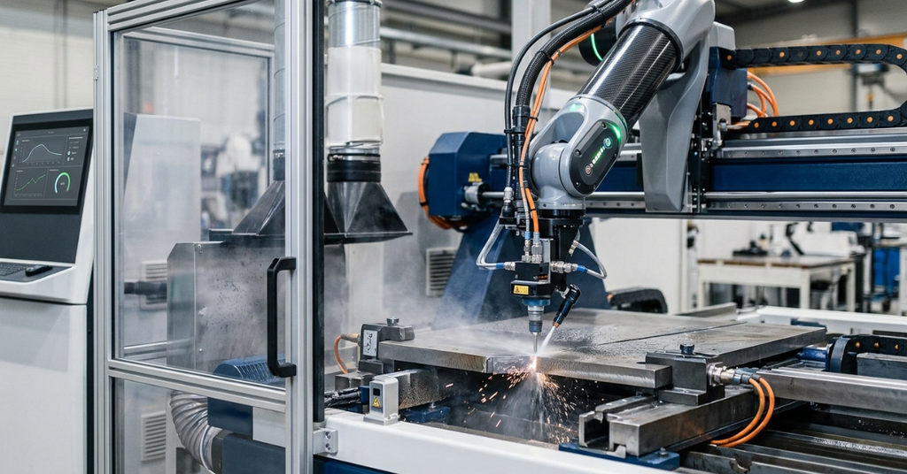
A typical system combines a robot arm, cutting head, motion controller, programming software, workholding equipment, and safety devices. Manufacturers can integrate these components into new production cells or connect them to existing CNC equipment.
Traditional CNC cutting machines usually follow predefined machine axes. An articulated robot can change the tool’s position and orientation across several axes. This flexibility helps manufacturers cut angled surfaces, curved profiles, pipes, and complex three-dimensional parts.
How Does Robotic Cutting Work?
Most robotic cutting systems follow a similar workflow:
- Create the part model: Engineers prepare a 2D drawing or 3D CAD model.
- Generate the toolpath: CAD/CAM software converts the design into cutting instructions.
- Configure the robot: Technicians define the robot’s position, tool orientation, workpiece location, and process parameters.
- Secure the material: Operators position the workpiece in a suitable fixture or cutting station.
- Calibrate the system: Technicians verify the tool center point (TCP), work coordinates, and required sensors.
- Execute the cutting program: The robot follows the programmed path while the cutting tool processes the material.
- Inspect the finished part: Quality teams check dimensions, edge conditions, and other specifications.
Manufacturers can add vision systems, laser scanners, or seam-tracking sensors to compensate for variations in part position. Using these features, the robot can follow the intended cutting path even when the workpiece is slightly different from the CAD model.
Where Do Manufacturers Use Robotic Cutting?
Industrial robotic cutting systems support several manufacturing sectors.
- Automotive: Cutting body panels, exhaust components, and structural parts.
- Aerospace: Trimming composite panels and processing selected metal components.
- Structural steel: Cutting beams, tubes, plates, and connection profiles.
- Shipbuilding: Processing large panels and complex structural sections.
- Metal fabrication: Cutting brackets, enclosures, frames, and custom components.
- Plastics and composites: Trimming molded parts and machining non-metallic materials.
- Construction equipment: Processing heavy-duty steel components.
The best application depends on the material, required geometry, production volume, and quality specifications.
Types of Robotic Cutting Systems
Manufacturers can choose from several cutting technologies. Each method offers different advantages in speed, edge quality, material compatibility, and operating cost.

1. Robotic Laser Cutting
Laser cutting uses a focused beam to melt, vaporize, or separate material. Fiber laser systems work particularly well with many metal sheets and profiles. They can produce narrow kerfs and clean edges when engineers match the laser settings to the material.
Best for: Precision metal fabrication, detailed profiles, and applications that require consistent edge quality.
2. Robotic Plasma Cutting
Plasma cutting uses an electrically conductive gas to cut electrically conductive materials. It offers a practical option for many steel fabrication jobs, especially when the material is too thick or the economics do not favor laser processing.
Best for: Structural steel, heavy fabrication, pipe profiles, and medium-to-thick conductive metals.
3. Robotic Waterjet Cutting
Waterjet cutting directs a high-pressure water stream through a small nozzle. Abrasive waterjets add particles to cut hard materials. The process avoids the thermal heat-affected zone associated with laser and plasma cutting.
Best for: Heat-sensitive materials, composites, selected metals, and applications that require cold cutting.
4. Robotic Mechanical Routing
A robotic router uses a rotating cutting tool to remove material. Engineers can program it to trim molded parts, machine plastics, and finish composite components. Tool wear, cutting forces, and dust control require careful management.
Best for: Plastics, composite trimming, non-ferrous materials, and selected machining tasks.
Robotic Plasma Cutting vs. Laser Cutting
Laser and plasma systems both use heat, but they serve different production needs.
| Factor | Fiber laser | Plasma |
| Typical strength | Fine details and narrow kerfs | Productive cutting of many conductive metals |
| Edge quality | Often cleaner on suitable materials | May produce more dross and a wider kerf |
| Thin materials | Usually a strong option | Can work, but heat input may affect thin parts |
| Thick steel | Depends on laser power and grade | Often attractive for heavy fabrication |
| Material limits | Depends on wavelength, power, and material | Requires electrically conductive material |
| Cost considerations | Source power and system integration affect cost | Torch consumables and cutting capacity affect cost |
| Main limitation | Higher initial investment in many configurations | Edge finish and dimensional control can require more work |
Neither technology guarantees a particular tolerance or finish. Engineers must test the actual material grade, thickness, cutting speed, and process settings before committing to production.
How Robotic Waterjet Cutting Improves Material Flexibility
Robotic waterjet cutting provides an important advantage when heat could damage the workpiece. It avoids the thermal heat-affected zone that laser and plasma processes create.
This makes waterjet cutting useful for many composites, plastics, and heat-sensitive materials. Abrasive systems can also cut numerous metals and hard materials.
However, waterjet systems introduce their own challenges. Pump energy, abrasive consumption, nozzle wear, water management, and workholding affect operating costs. Waterjet cutting also does not automatically deliver better dimensional accuracy than every thermal process.
Gantry vs. Articulated-Arm Cutting Systems
Manufacturers often compare gantry machines with articulated robot arms when they design a cutting cell.
| Feature | Gantry system | Articulated robot |
| Motion | Linear axes across a defined work envelope | Rotational joints that change position and orientation |
| Best use | Large, relatively flat workpieces | Complex three-dimensional parts |
| Work envelope | Often rectangular and predictable | Flexible, but affected by reach and joint limits |
| Tool orientation | Depends on installed axes | Well suited to multi-angle cutting |
| Integration | Can fit established CNC workflows | Often requires robot-specific programming and calibration |
A gantry system can deliver strong rigidity and predictable motion for large flat sheets. An articulated arm can reach around curved surfaces and follow complex profiles. Some applications combine both approaches by mounting a robot on a linear track.
Key Components of Industrial Robotic Cutting Systems
A robotic cutting cell requires more than a robot arm. Every component contributes to cutting quality, reliability, and operator safety.
1. Six-Axis and Multi-Axis Robotic Arms
A six-axis articulated robot uses six rotational joints to position and orient its tool. This configuration can follow complex paths and cut surfaces from multiple angles.
Some applications need additional motion. A seventh axis, such as a linear track, extends the robot’s reach along a work area. Other systems combine a robot with external positioners that rotate or tilt the workpiece.
When selecting a robot, evaluate:
- Payload: Include the cutting head, cables, sensors, and other tools.
- Reach: Confirm that the arm can access every cutting point.
- Repeatability: Check whether the robot can return to programmed positions consistently.
- Wrist orientation: Ensure the robot can achieve the required cutting angles without joint-limit conflicts.
- Rigidity: Assess how arm deflection and vibration could affect the finished edge.
Robot repeatability does not equal finished-part accuracy. Calibration errors, fixture movement, thermal effects, and cutting-process variation also influence results.
2. Cutting Heads and Process Equipment
The end effector performs the actual cutting operation. A laser cell may use a fiber laser cutting head, while a plasma cell needs a torch and compatible power supply.
Waterjet cells require a high-pressure nozzle and, where necessary, an abrasive delivery system. Mechanical routing cells need a spindle, suitable cutting tools, and tool-change or maintenance procedures.
The end effector must be matched to the robot’s payload, mounting interface, operating environment, and cutting process.
3. Sensors, Fixtures, and Tool Calibration
Sensors help robotic cutting systems respond to real-world variations. A laser scanner or vision system can locate a workpiece. A seam-tracking sensor can help the robot follow a joint or profile.A collision sensor can protect equipment when it encounters an obstruction.
Fixtures hold parts in a repeatable position. Poor workholding can undermine an otherwise accurate cutting program.
Tool center point (TCP) calibration establishes the cutting tool’s reference point relative to the robot flange. Engineers also need accurate workpiece coordinates. Incorrect calibration can create path offsets, inconsistent edge quality, and collisions.
4. CAD/CAM Software and Robot Controllers
CAD/CAM software converts part geometry into cutting paths. Robot simulation and offline programming tools let engineers inspect reach, tool orientation, collision risks, and cycle sequences before production.
The robot controller executes the program. Process controllers manage functions such as laser power, plasma current, gas flow, or waterjet operation.
Manufacturers should verify compatibility among the robot brand, controller, cutting equipment, postprocessor, and safety system before purchasing a complete cell.
Robotic Cutting Technology Comparison and Performance Benchmarks
Manufacturers should compare cutting technologies using measurable production requirements rather than marketing claims. Four useful metrics include cycle time, dimensional accuracy, capital expenditure (CapEx), and material utilization.

- Cycle time: Measure the time required to complete a part or production batch.
- Dimensional accuracy: Compare the finished part with its drawing or CAD model.
- The capital expenditure includes the robot, cutting source, fixtures, software, enclosure, extraction, and installation.
- Material utilization: Calculate the proportion of purchased material that becomes usable product.
Illustrative Technology Comparison
The following table provides indicative planning ranges and qualitative comparisons. It does not represent a verified laboratory benchmark or a controlled test of all four technologies. Actual results depend on equipment configuration, material grade, thickness, path geometry, and process settings.
| Technology | Illustrative tolerance target | Edge finish | Changeover considerations | Typical application | Relative investment |
| Robotic fiber laser | Around ±0.1 mm in suitable setups | Fine, with low roughness possible | Program and fixture changes | Precision metal parts | Often high |
| Robotic plasma | Around ±0.5 mm in suitable setups | More variation and possible dross | Torch setup and consumables | Structural steel | Medium to high |
| Robotic waterjet | Around ±0.2 mm in suitable setups | No thermal HAZ; finish depends on settings | Fixturing and abrasive setup | Composites and mixed materials | Often high |
| Robotic mechanical router | Around ±0.3 mm in suitable setups | Depends on tool, material, and feed rate | Tool changes and wear checks | Plastics and composite trimming | Varies |
Note: Treat the tolerance figures as preliminary engineering targets, not guaranteed machine specifications. The edge-finish values in the original outline also require measurement conditions and test data before publication.
How to Run a Reliable Benchmark
A meaningful comparison requires a controlled test.
- Select the same material grade and equivalent workpiece geometry.
- Define identical dimensional and edge-quality requirements.
- Include loading, unloading, setup, cutting, and inspection in the cycle-time measurement.
- Measure dimensional deviation at defined points.
- Record consumables, energy use, labor, and maintenance.
- Calculate material utilization using the same nesting rules.
- Repeat the test and document the sample size.
Engineers should report the mean, variation, test conditions, and measurement method. They should also explain whether they tested a production machine, a prototype, or a simulated workflow.
Without these details, a table of precise numbers can give readers more confidence than the evidence supports.
How to Integrate Robotic Cutting into Existing CNC Lines
Manufacturers do not always need to replace their current equipment. Robotic cutting can be introduced into selected stages of an established production line.
Step 1: Audit the Current Process
Map the existing workflow from material loading to final inspection. Identify manual cutting, repeated setups, handling delays, scrap, and bottlenecks.
Collect baseline data before choosing equipment. Record cycle time, labor hours, first-pass yield, scrap rate, and maintenance costs.
Step 2: Select the Right Integration Method
Manufacturers can use several approaches:
- Standalone robotic cell: Suitable for a dedicated cutting operation.
- Robot beside an existing CNC machine: Useful for loading, unloading, or processing selected features.
- Robot with a linear track: Extends reach across longer parts or multiple workstations.
- Connected production cell: Coordinates robots, CNC equipment, conveyors, fixtures, and inspection systems.
The right choice depends on the existing layout, production mix, and required throughput.
Step 3: Connect CAD/CAM and Production Data
A compatible CAD/CAM workflow reduces manual programming and helps engineers reuse part definitions. Offline programming allows teams to prepare and simulate robot paths while production continues on the shop floor.
However, simulation alone cannot guarantee collision-free production. Engineers must verify the actual robot, tooling, fixtures, cables, and workpiece.
Step 4: Validate the Cell Before Full Production
Run a pilot with representative parts. Check dimensional accuracy, cycle time, edge quality, operator access, and maintenance requirements.
Train operators and technicians before increasing production volume. Establish backup procedures, program version control, and recovery steps for interrupted cycles.
Step 5: Track Production Results
Compare the new cell against the baseline. Measure scrap, throughput, downtime, tool consumption, and total cost per acceptable part.
Keep the system only if the measured benefits support the investment and the process meets quality and safety requirements.
Case Study: Evaluating a Robotic Plasma Cutting Upgrade
Consider a structural steel manufacturer that wants to replace manual torch cutting and some conventional CNC-table operations with a six-axis robotic plasma cutting cell.
The company processes beams, plates, and complex profiles. Operators frequently adjust cutting paths, and the factory experiences scrap from inconsistent part positioning and inefficient nesting.
The following scenario illustrates how a manufacturer could evaluate an upgrade. The figures are illustrative targets supplied in the proposed outline, not independently verified results from a documented customer installation.
The Implementation Method
The manufacturer could follow four steps.
1. Introduce offline programming. Engineers import 3D CAD models into compatible CAD/CAM software. They generate robot paths and simulate the cutting sequence before production.
2. Improve material nesting. The team arranges part profiles to reduce unused space in each plate or sheet. Engineers must also account for cut spacing, edge conditions, and the manufacturer’s quality requirements.
3. Add part-location sensing. A laser scanner or suitable sensing system identifies workpiece position. The controller can then compensate for defined placement variations.
4. Establish production measurements. The team records scrap, linear cutting output, downtime, and acceptable-part yield before and after installation.
Illustrative Results and Their Meaning
| Metric | Proposed result | Evidence needed |
| Raw material scrap reduction | 38% | Comparable material input and scrap records |
| Linear cutting output | 4.2 times baseline | Defined cutting length per operating hour |
| Payback period | 14.2 months | Documented project costs and verified net savings |
These results should not serve as universal performance promises. A manufacturer should publish them as actual case-study findings only after verifying the source data, measurement period, and comparison method.
The results also depend on more than the robot. Better nesting may reduce material waste, while offline programming may reduce setup delays. Seam tracking may improve path consistency. A sound evaluation should isolate these effects where possible.
The 5-Point Robotic Cutting Cell Evaluation Framework (RCEF)
Choosing robotic cutting options should be compared consistently among manufacturers.The following Robotic Cutting Cell Evaluation Framework (RCEF) offers a practical decision method for early-stage planning.
This framework represents a proposed evaluation method, not a validated industry standard. Teams should adapt its criteria to their application and confirm the final design through engineering tests.
1. Material Sensitivity Index (MSI)
Start by evaluating how the material responds to heat, mechanical force, and water.
Ask these questions:
- Can the material tolerate a thermal cutting process?
- Will heat affect its strength, coating, or surface?
- Does the application require a cold-cutting process?
- Can the material withstand abrasive contact or mechanical tool pressure?
It is possible to cut many conductive metals using lasers and plasmas. Waterjet cutting can help when heat poses a concern. Mechanical routing can suit plastics and composite trimming.
2. Geometrical Complexity Factor (GCF)
Evaluate the part’s shape and the cutting tool’s required orientation.
A flat sheet may need only simple motion. A curved pipe or complex structural component may require several axes of movement.
Consider the following options:
- Three-axis motion: Suitable for many flat, two-dimensional cutting jobs.
- Five- or six-axis motion: Supports angled cuts and complex three-dimensional profiles.
- Seven-axis configurations: An additional linear track can extend reach across larger work areas.
The correct configuration depends on tool orientation, robot reach, joint limits, collision risks, and fixture design.
3. Volumetric Throughput Rate (VTR)
The cutting cell must be able to handle a certain amount of productionConsider both cutting speed and non-cutting activities.
A robot may cut quickly but still deliver poor overall throughput if operators spend too much time loading parts or changing fixtures.
Use this formula:
Throughput=AcceptedpartsOperatinghours
Measure accepted parts rather than raw cutting output. This approach accounts for rejected components and quality problems.
4. Tolerance Accumulation Analysis
Identify every source of dimensional variation.
Robot repeatability represents only one part of the accuracy equation. Tool calibration, fixture tolerances, material deformation, sensing errors, and cutting-process variation also influence the finished part.
Create a tolerance budget for the complete cell. Validate it with representative workpieces and suitable inspection equipment.
Do not assume that a robot with excellent repeatability will automatically deliver the same accuracy at the cutting edge.
5. Safety and Environmental Footprint (SEF)
Before selecting equipment, consider the safety and environmental requirements of the cell.
Consider:
- Machine guarding and access control.
- Laser protection or plasma arc shielding.
- Fume extraction and particulate filtration.
- Noise exposure and hearing protection.
- Water management and abrasive disposal.
- Electrical safety and emergency stops.
- Maintenance access and lockout procedures.
Use the applicable regulations and standards to guide the design. A qualified safety professional should assess the complete cell, including its robot, cutting equipment, fixtures, and operator interfaces.
RCEF Decision Matrix
Score each category from 1 to 5. A higher score should indicate a stronger match between the proposed system and the manufacturer’s requirements.
| Evaluation category | What the score should reflect |
| MSI | Compatibility with material and thermal requirements |
| GCF | Ability to reach and cut the required geometry |
| VTR | Capacity to meet production demand |
| Tolerance analysis | Ability to meet dimensional specifications |
| SEF | Ability to meet safety and environmental requirements |
Add the five scores to produce a preliminary total from 5 to 25.
Use this score to compare shortlisted concepts, not to approve a purchase automatically. A low safety score, for example, should trigger corrective action regardless of the overall total.
Robotic Cutting Programming, CAD/CAM, and Process Optimization
Programming determines how effectively a robotic cutting system converts a part design into a finished component.

Offline Programming and Simulation
Offline programming (OLP) lets engineers develop robot programs away from the production cell. They can import CAD models, generate toolpaths, check robot reach, and identify potential collisions.
This approach can reduce shop-floor programming demands. However, engineers still need to validate the program on the physical system.
The simulation must reflect the installed robot, cutting head, fixtures, workpiece, external axes, and relevant safety restrictions.
Tool Center Point Calibration
TCP calibration defines the cutting tool’s reference point relative to the robot flange. Accurate calibration helps the controller position the tool along the intended path.
A practical calibration workflow includes:
- Inspect the tool mounting and check for damage.
- Use the robot manufacturer’s approved calibration method.
- Verify the TCP against a suitable reference.
- Check workpiece coordinate frames.
- Run a controlled test path.
- Inspect the result and correct any measured offsets.
Recheck calibration after a tool change, collision, or maintenance activity when the event could affect tool geometry.
Feed Rate and Kerf Optimization
The feed rate controls how quickly the tool moves through the material. The kerf describes the width of material the cutting process removes.
Engineers should balance cutting speed, edge quality, dimensional accuracy, and consumable life. Excessive speed can compromise cut quality, while unnecessarily slow settings can increase cycle time and heat exposure.
Create process recipes for validated material grades and thicknesses. Record cutting speed, power or current, gas settings, nozzle condition, and other relevant parameters.
Robotic Cutting Safety Standards and ISO Compliance
Robotic cutting cells combine moving machinery with process-specific hazards. Manufacturers must address those hazards during design, installation, operation, and maintenance.
ISO 10218 and ANSI/RIA R15.06
The ISO 10218 series addresses industrial robot safety. ANSI/RIA R15.06 provides the corresponding US industrial robot safety framework, aligned with relevant ISO requirements.
Teams should verify the current editions and applicable national requirements before designing a cell. They should also determine which standards apply to the complete machinery installation rather than focusing only on the robot arm.
A robot’s built-in safety features do not automatically make the entire cutting cell safe.
Essential Safety Measures
A suitable risk assessment should examine:
- Robot movement and unexpected restart.
- Cutting arcs, laser radiation, and hot material.
- Flying particles, fumes, and airborne contaminants.
- High-pressure waterjet equipment.
- Mechanical tool contact and collision hazards.
- Electrical hazards and stored energy.
- Access during setup, troubleshooting, and maintenance.
Depending on the application, the cell may require physical guarding, interlocked access doors, safety-rated sensing, extraction systems, and controlled maintenance procedures.
Manufacturers should also train operators, document safe operating procedures, and verify safety functions during commissioning and maintenance.
How to Calculate Robotic Cutting ROI and Payback
Robotic cutting can reduce manual handling, improve repeatability, and increase production flexibility. However, these benefits do not guarantee a positive financial return.
A realistic ROI calculation should include all project costs and measurable operating savings.
Initial Investment Costs
Include the following expenses:
- Robot and cutting equipment.
- CAD/CAM and offline programming software.
- Fixtures, sensors, and material-handling systems.
- Safety enclosure and extraction equipment.
- Installation, integration, and commissioning.
- Operator training and production validation.
Also account for financing, maintenance, utilities, consumables, and any production disruption during installation.
Calculate Annual Net Savings
Use this formula:
AnnualNetSavings=AnnualOperatingSavings-AnnualAddedCosts
Operating savings may include reduced scrap, lower labor requirements, less rework, and additional contribution from increased output. Avoid counting the same benefit twice.
Then estimate simple payback:
PaybackPeriod(months)=InitialInvestmentAnnualNetSavings12
This formula assumes positive annual net savings. It also excludes the time value of money and changes in savings over time.
Example ROI Calculation
Consider a hypothetical metal fabricator evaluating a robotic cutting cell.
| Financial item | Illustrative amount |
| Initial investment | $300,000 |
| Annual operating savings | $150,000 |
| Annual added operating costs | $30,000 |
| Annual net savings | $120,000 |
| Simple payback period | 30 months |
The calculation uses $300,000 divided by $120,000, multiplied by 12 months.
These figures illustrate the method rather than predict a typical industry result. Each manufacturer should use its own production, labor, scrap, and operating-cost records.
Interactive ROI Calculator
Use this simple calculator to explore how different investment costs and annual savings affect payback.
Frequently Asked Questions
1. What is robotic cutting technology?
Robotic cutting technology uses programmable industrial robots to guide laser, plasma, waterjet, or mechanical cutting tools. Manufacturers use it to process complex shapes and automate repetitive cutting operations.
2. Which robotic cutting method offers the best accuracy?
No single method delivers the best accuracy in every application. Laser cutting can produce fine features on suitable materials, while waterjet, plasma, and mechanical routing serve different needs. Engineers should validate accuracy with representative parts and suitable inspection methods.
3. Is robotic plasma cutting better than laser cutting?
Plasma cutting often suits structural steel and many heavy fabrication jobs. Fiber laser cutting often suits applications that require fine details and narrow kerfs. Material thickness, equipment cost, production volume, and edge requirements determine the better choice.
4. Can manufacturers integrate robotic cutting into existing CNC lines?
Yes. Manufacturers can add a standalone robot cell, connect a robot to an existing CNC machine, or integrate robots with conveyors and material-handling systems. They must check software compatibility, layout, safety, and production requirements.
5. How much does an industrial robotic cutting system cost?
The cost depends on the robot, cutting source, payload, work envelope, software, fixtures, safety equipment, and integration work. Manufacturers should request complete system quotations rather than compare robot prices alone.
6. How long does robotic cutting automation take to pay back?
The payback period depends on the initial investment and verified annual net savings. Manufacturers should calculate labor, scrap, rework, consumables, maintenance, and throughput changes using their own production records.
7. Which standards apply to robotic cutting safety?
ISO 10218 and ANSI/RIA R15.06 provide important industrial robot safety frameworks. The complete cell may also need to meet other applicable machinery, electrical, laser, environmental, and workplace safety requirements.
8. Does a six-axis robot always outperform a three-axis CNC machine?
No. A six-axis robot offers greater tool-orientation flexibility, but a conventional CNC machine may provide better rigidity or accuracy for certain jobs. The part geometry and process requirements should guide the comparison.
9. What role does CAD/CAM software play in robotic cutting?
CAD/CAM software converts part geometry into cutting paths and process instructions. Offline programming and simulation help engineers prepare programs, check robot reach, and identify potential collisions before production trials.
10. What should manufacturers evaluate before purchasing a robotic cutting cell?
Evaluate material compatibility, cutting quality, cycle time, dimensional accuracy, robot reach, payload, software, safety, maintenance, and total ownership cost. Run a pilot test before committing to full-scale deployment.
Conclusion
Robotic cutting technology gives manufacturers a flexible way to automate complex cutting tasks and improve production consistency. Laser, plasma, waterjet, and mechanical routing systems each offer distinct advantages. The right choice depends on material properties, geometry, quality requirements, throughput, and cost.
Manufacturers should test candidate systems, verify safety requirements, and calculate ROI using actual operating data. A structured evaluation process helps teams choose equipment that meets production needs without relying on unverified performance claims.

I am Qasim Ali, a technology enthusiast passionate about exploring the latest innovations shaping our digital world. With 5+ years of experience in technology and digital trends, I share practical insights on AI, software, hardware, cybersecurity, programming, and emerging technologies. Through Techvens, my goal is to simplify complex technology and help readers stay informed, confident, and ahead in the fast-moving tech world.